TL;DR Choosing the right mould material and design affects surface finish, tolerances and cost. Match a material to the casting method and part requirements, use straightforward gating and venting, and run simple checks before production to reduce rework.
Designing a mould for metal casting starts with a tight brief: what metal, what finish, the tolerances you need and how many pieces are required. This article walks through the material choices you are likely to meet in a specialist foundry, the key design decisions for patterns, gating and vents, and a practical production checklist to use before sending files to a workshop. For broader commissioning guidance, see Custom Metal Casting: How To Choose The Right Foundry for questions to ask potential suppliers.
Key considerations for selecting mould materials
Start by prioritising three factors: the alloy and pouring temperature, the acceptable surface quality, and batch size. These determine which mould family is suitable and the likely finishing work after casting.
Higher pouring temperatures and reactive alloys need more robust, refractory moulds. If surface definition matters and the part has fine detail, choose materials that reproduce texture accurately and resist erosion during metal flow. For small runs or prototypes, lower-cost flexible moulds can reduce lead time.
Cost and turnaround also matter. Reusable mould systems such as metal or ceramic tooling can be economical for larger runs, while single-use sand or investment moulds are common for one-off sculptures or short production runs. Each option trades durability against fidelity and cost; the rest of the article explains those trade-offs so you can match the choice to the brief.
Materials commonly used for casting moulds
Foundries typically work with a handful of established mould families. Each has predictable properties that influence design and finishing.
- Green sand and bonded sand , inexpensive and adaptable. Sand moulds cope with large volumes and bulky shapes but usually need more fettling and produce a rougher surface than investment methods.
- Investment (lost‑wax) moulds , excellent for fine detail and smooth finishes. They are suitable for complex geometry and thin sections but are single use and have longer lead times due to wax and ceramic shell processes.
- Refractory ceramic moulds , used where dimensional stability at high temperatures is essential. Ceramic moulds can deliver high accuracy for reactive or high‑temperature alloys.
- Rubber and silicone moulds , typically used for low‑temperature non‑ferrous castings or as pattern tools. They reproduce texture well and are useful for short runs or prototyping, but have temperature and wear limits.
- Metal tooling , steel or aluminium toolings are durable and reusable; appropriate for larger production runs where upfront tooling cost is justified by repeatability and throughput.
When the brief specifies bronze or other traditional alloys, verify whether the chosen mould material resists chemical attack and thermal shock. Ask for reference castings if surface finish or patina response is critical.
Designing patterns, gating and venting
A good pattern and gating layout helps metal flow predictably and reduces defects. Keep the design pragmatic: avoid unnecessarily thin sections, provide radii at stress concentrations and think about how the part will be removed from a single or multipart mould.
Key rules to apply:
- Place gates where the metal can fill cavities without trapping air; for long thin sections consider multiple feed points.
- Design risers to supply shrinkage-prone areas and to act as visible sacrificial points for finishing.
- Include vents or use permeable mould materials to allow gases to escape; blocked vents are a common cause of porosity.
- Orient parts to minimise complicated cores and to make pattern removal feasible without damaging detail.
Small changes at the pattern stage can save significant finishing time. For example, blending abrupt section changes reduces turbulence during filling, which in turn reduces oxides and cold shuts.
Practical checks engineers should run
Before finalising the pattern, run a short checklist: confirm minimum section thicknesses for the chosen alloy, identify likely shrinkage zones, check draft angles for pattern extraction, and ensure fillets are present at internal corners. If using cores, check their support and location relative to gates.
If simulation is available, use a basic flow and solidification run for complex parts. For simpler work, a peer review of gating and vents against previous successful castings is often sufficient.
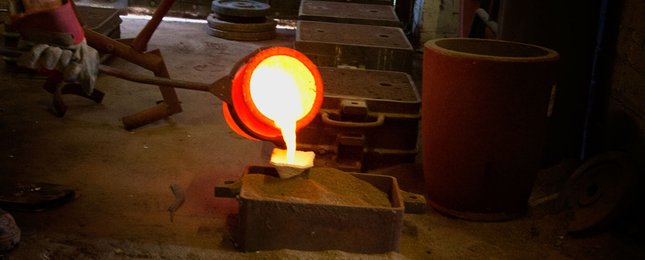
A typical mould production process , step by step
The exact sequence depends on the chosen method, but most workflows follow these stages: pattern or master production, mould preparation, metal pouring, cooling and cleaning, and finishing. Below is a condensed checklist to share with a foundry.
- Confirm part specifications: alloy, dimensions, tolerances, surface finish and run quantity.
- Produce a master pattern (CNC, 3D print, hand model). Check scale and detail reproduction.
- Prepare the mould system: assemble cores, build sand or ceramic shells, or set up metal tooling.
- Fit gating and vents, and position risers. Recheck orientation and access for pouring.
- Pour under controlled conditions; monitor temperature and pour rate where possible.
- Allow appropriate cooling time to avoid hot tearing. Remove the casting from the mould and conduct initial inspection.
- Perform fettling, machining and surface finishing as specified. Check critical dimensions and surface finish against the brief.
A short production trial cast can validate the layout and reduce the risk of an expensive re-run. Where feasible, discuss a single trial piece with the foundry to confirm finish and tolerances before committing to a larger batch.
FAQ
Choose sand moulds when you need a robust, economical option for larger parts, simpler geometry or shorter lead times, and where a slightly rougher surface finish and more fettling are acceptable. Choose investment (lost‑wax) moulds when fine detail, thin sections and superior surface finish are priorities, and you can accommodate higher tooling effort, single‑use shells and longer lead times.
Minimum wall thickness depends on alloy, casting method and part size, but many foundries treat 3–4 mm as a sensible lower limit for general bronze work in sand or similar processes. For thinner walls, intricate geometry or demanding tolerances, discuss the design with the foundry early and consider investment casting or local thickening, fillets and ribs to keep sections castable while still meeting weight and performance targets.
Yes. 3D printing is widely used to produce master patterns, short‑run tooling and even sacrificial patterns or cores for investment and sand processes, especially when geometry is complex or you need fast iteration. When you plan to print patterns, coordinate material choice, tolerances and any post‑processing with the foundry so the printed parts suit their mould system, shrinkage allowances and surface‑finish expectations.
Summary and what to do next
Match the mould family to temperature, detail and run size, design gating and vents to encourage clean filling and feed shrinkage, and run a short checklist or trial casting to validate the approach. Early conversations with a specialist foundry will align pattern choices with production realities and expected finishes.
If you are preparing technical files for a supplier, include alloy specification, critical dimensions and a preferred surface finish note. For guidance on selecting a partner to cast your parts, refer to Custom Metal Casting: How To Choose The Right Foundry which lists practical supplier questions and project considerations.